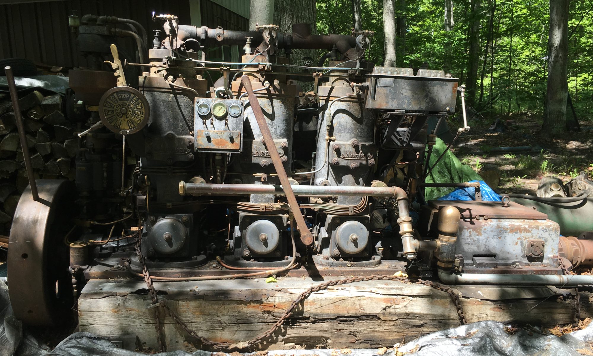
Getting ready for bearings

I recently realized it has been a year (and a day) since my last update. While a little work has been getting done, I’ve mostly been waiting on bearing work although it has been such a busy year I’ve not pressed the job. But now it is time to get the project back on track and moving forward. I have other projects to tackle and the Kahlenberg is taking up a lot of shop space. And I want to hear it run!

My first step in the bearing process was to set up the line boring equipment. George (the babbitt guy) has all the equipment and gave it to me to prepare. He hasn’t done a job this large so there is some new territory. I’ve already blogged about making the fixture for pouring babbitt in the large main bearings. Now I needed to set up the line bore. The bridges mount to parallel bars. The first trick was attaching the parallel bars to the block. I made a dozen clamps and bolted them to the existing cylinder base mounts which provides excellent strength around the main bearings. I had to use regular c-clamps to attach the bars near the #5 output bearing.

Once the bridge bars were securely attached, I then mounted the bridges and ran the boring bar through each bridge. Centering the boring bar required making centering plugs. I couldn’t find suitable commercial units so I made them out of aluminum. This took some time with my modest mill and lathe but they came out well. These aluminum plugs sit in the bearing saddle with the caps properly installed and torqued. This allowed setting the boring bar within, I’m estimating, a few thousandths of center through the entire nine feet.

I went back and forth adjusting the bridges but got the bar centered and running smoothly without difficulty. There is a gearbox to slowly advance the cutter which is powered by a geared motor. It is kind of amazing how easy it is to set up this whole rig for a novice like me. A clever design and very well-made. The machine was manufactured by Kwik-Way of Marion, Iowa. The manual is dated 1979 and apparently was originally shipped to the Army in Rock Island, Illinois.

Line bore set up and ready to make bearings.

Other tasks completed over the past year included making about a dozen bolts from hex stock. You can’t buy these from McMaster-Carr.

2 old (and bent) bolts with two new bolts

This is the jig I made for pouring babbitt into the bearing shells.

fixture for pouring babbitt with a rod bearing half installed

Other tasks this past year included finishing rebuilding the air starter, overhauling the three fuel injector pumps and rebuilding one of the water pumps. This pump circulates cooling water. I still have another water pump to do although the second one (starboard side) was used as a bilge pump in the boat so won’t be used now. In fact, the internal pump valving had been removed prior to my getting the engine. I’m starting to run out of things to do before the engine starts going back together, hopefully soon!

Main Bearings

The last major task remaining before reassembly begins is addressing the main and rod bearings. An earlier post includes pictures of the #5 main bearing, the tail bearing on the output shaft, which is in bad shape. The four main crankshaft bearings are in decent to very good condition. I reinstalled the bearing shells and placed the crankshaft back in the main block. I then torqued the caps and used Plastigauge to measure the bearing clearances. Surprisingly, all the clearances are between .003 and .008, which on a 3.5″ shaft is not bad for a machine of this vintage.

Moving crankshaft back into the engine block for bearing checks.
Checking bearing clearances with Plastigauge

I’m very fortunate to have a well known babbitt specialist just 15 minutes from my house. George owns Harkin Arcola Babbitt Repair. He has been to my shop a few times to size up the bearing situation. We decided to not re-pour the main bearings other than the damaged #5 shells. This is fortunate because this is the shortest bearing. The others are up to 11″ long. George is going to attempt to make minor repairs to a few of the shells that have small cracks.

However the rod bearings have much more serious cracks in the babbitt so these will be re-poured. I am working on building a jig to hold the bearings during the babbitt pouring process. More on this in a following post.

One big item that has been gnawing on me for some time is the #1 bearing cap. This is the cap that was cracked and repairs by another shop only made matters worse. I discussed this in the prior post. After a lot of discussion, George and I decided to leave the cap as-is. I am not able to maintain perfect and repeatable alignment but we decided on a method that should get the cap located close to where it should be and within reasonable tolerances. Worst case, if it doesn’t work, the cap is easily accessible after the engine is reassembled and other attempts at repairs can be made. The only thing I have to do is make cap bolts. Two of the existing bolts are stretched and bent. I bought some 1″ hex rod and will be working on these in the lathe this week.

Pinch Hitter

We had a visitor in the shop last week. Kurt Krueger restored a Kahlenberg a few years ago and donated it to the Door County Maritime Museum in Gills Rock. I’ve been communicating with him for five years but we had not met in-person. Kurt decided to make the trip from eastern Wisconsin and stayed with us for a couple days. Even though I couldn’t completely escape from work commitments, he worked in the shop doing a number of very helpful things. Kurt is a wealth of information and very generous with his time. Below is a picture of Kurt (in the back) with his engine:

Kurt Krieger (in the rear) with his restored Kahlenberg at the Door County Maritime Museum in Gills Rock WI

One huge difference between Kurt’s restoration and mine is that his engine started as a rusted hulk in awful condition after having sat outside for decades. My engine was kept in fairly good condition with minimal damage from the elements. He had many parts that had to be fabricated from scratch because the originals had basically disintegrated. Just getting his pistons out of the cylinders was a challenge.

Kurt assisted me with repairing one of the fuel injector pumps, the cracked manifold and made a big number of gaskets that I will need soon.

I’ve been deliberating on what to do with the crack in the exhaust manifold. Welding seems to be out of the question, or at least not without a lot of risk. Tapered iron plugs was another option but I was having trouble getting comfortable with that repair method. Since the water isn’t at a very high pressure level, I considered doing nothing at all and just letting it leak. But that might lead to longer term issues. It might be considered a hack by some (including me) but we decided to grove out the crack and fill with epoxy. I’m hoping this repair lasts but I could always go back to the tapered iron plugs. It passed the pressure test.

I’ve had the disassembled fuel injector pumps on my bench for a few months. There is one pump for each cylinder. An injector pump is a block of brass that has a plunger piston operated from the governor tower. There are two valves in the block, input and outlet fuel. One of the valves was stuck in the seat deep in the block. I had it soaking for a couple months but it refused to come out. There is very little to grab on the valve. Oddly, all the valves had a slot cut in the top to allow lapping to be done with a screwdriver but the one that was stuck did not have such a grove. We decided that the only option was to drill a hole in the bottom of the block directly underneath the valve so we would punch it out. This worked well but that valve was stuck in the seat pretty good. There had obviously been water in there and some rust had frozen it in place. We cut a new groove in the valve, cleaned it up and lapped it back in place. We then tapped the drilled hole and sealed it with a brass screw. All three pumps feel like they are working but of course will need to be tested.

The last task in my way before the main bearing work is the number one bearing cap. The repairs done by the shop a couple years ago are turning out to be more harm than good. The caps are held in place with 4 bolts and 2 taper pins. I did not discover until recently that the shop drilled out the tapered holes so I’ve lost the ability to accurately locate the bearing cap. Fortunately they did not drill out the block but just the cap. I’m considering bolting in place and reaming oversized holes into the block. There are some challenges with this that I won’t go into right now but short of finding another bearing cap, I’m out of ideas. I will see if my bearing guy has any other ideas.

#1 bearing cap

Exhaust Manifold Crack

One of the last big pieces to get attention was the exhaust manifold. It received a first-pass cleaning before it came off the engine but has been sitting on a cart ever since. I gave it a good cleaning and prepped it for painting. After the primer was applied it became obvious that what I thought was a casting mark is actually a crack below the middle clean-out port, most likely from a freezing water jacket based on the location near the bottom.

Exhaust Manifold
Exhaust Manifold
Exhaust Manifold Crack

I loaded up the manifold for a trip to the welder. (It’s heavy. It squatted my 3/4 ton truck pretty good. Guessing maybe 600 pounds.) He thinks there is some risk in welding and suggested a tapered plug repair. I’m going to install the end plates, seal the openings and do a pressure test. Looking at pictures in hindsight shows a little bit of leakage evidence but no idea how long the crack has been there. The pressure test will tell me if I need to do something about it. Just waiting on more gasket material to arrive for the end plates. (Like a lot of things right now, some materials are hard to get. Been waiting two months for the large gasket material I need.)

More painting, air intakes, air distributor and another running Kahlenberg

A few months back I was debating whether to paint the engine or let it stay in its vintage patina. I was leaning towards keeping it as-is but changed my mind. There was a lot of peeling paint of various generations plus blobs of other paint most likely from the interior of the fish tug. And quite a bit of rust. As a (hopefully) running engine going forward, it’s going to get coated in oil anyway. Regardless, I’m committed now. The main color is “cast coat iron” with a darker machinery gray for various other components like the oilers, flyweight housing, heads and maybe a few other things. I also decided to not attempt painting the foundation but might change my mind on that one.

Governor tower base prepared for painting
Painted cylinder

One of the subassemblies I worked on recently was the dial control. This runs from the throttle/timing control back to the air starter valve. Surprisingly, the timing shaft and control cam are serialized. Overall, it was in pretty good condition. This assembly is also interesting because it is obviously designed later than the engine. There were at least three types of control systems available. This one is the “C” family so probably the third generation. It includes cap screws, flange nuts and zirk fittings, things not seen anywhere else on the engine.

Dial control
Dial control shaft for injection timing
Dial control cam for injection timing
Refurbished dial control

The air intakes were up next. They were disassembled and given a thorough cleaning before painting. These are interesting mechanisms. Being a valveless two-stroke engine, intake air is drawn in through the crankcase. The air intake valves are similar to a modern reed block. In this case the reeds are round brass disks. The disks are held closed by a series of coil springs. Vacuum caused by the piston moving upward pulls the reeds open to draw in air. I’m not sure how the engineers arrived at using disks but it is clever and simple. It is also very easy to work on. There are two of these per cylinder, one on each side of the cylinder base. Once again I was lucky to find the intakes in good condition. There were a couple of springs to replace but the brass reeds were fine.

Air intake ready for reassembly
Refurbishing complete on one of the six air intakes

Currently on the bench is the air starter distributor. This times the compressed air to each of the cylinders for starting. The air distributor has one of the few ball bearings in the engine. Unfortunately the bearing is in rough shape from rust. I did a search based on the information on the bearing and surprisingly the company is still in business (Aetna Bearing). I ordered a replacement for $37 direct from the manufacturer.

Air distributor
Air distributor

I still have quite a bit of cleaning and painting including a few large items like the exhaust manifold and transmission case. The weather has been very conducive to painting so I’m trying to get as much done this month as possible. I’m not trying to strip down to bare metal but to just get the loose paint off and smooth it out a bit. Below are the intake port inspection plates and the only castings with the “Kahlenberg” script.

Cleaning inspection plates

I visited the “Albany Pioneer Days” threshing show this past weekend. I had heard there was a Kahlenberg on display and sure enough:

Kahlenberg at Albany MN owned by the Stearns County Pioneer Club

This is a B-series engine which has a 10″ bore. Mine is a A-series with 8.5″ bore but otherwise a lot of common parts. I got to see it run and talk with the curator. Another good source for information! It’s very enjoyable to talk with other Kahlenberg people.

Cleaning and Painting

It’s been a quiet summer for the Kahlenberg. We’ve been spending a lot of time outside and in the garden along with a couple of week-long vacations and family get-togethers. Most recently I stripped the foundation base to its bare minimum. I decided to not pass up the opportunity to give the base a thorough cleaning so it was loaded up on a trailer for a trip to the self-service car wash. I washed the underside at the car wash and then brought it home, flipped it over with the crane and power washed the top/inside. The bottom of the foundation had a much thicker buildup of grime so I didn’t want that crud in the driveway

Taking the foundation to the car wash for a thorough cleaning
Cleaned foundation base back in the cradle

The cylinder bases also received a power washing but these were manageable enough to be by myself in the driveway. The trailer made a good platform.

Now is the opportunity to paint these large pieces. I masked off what was necessary and delivered a couple coats of cast iron gray.

I’ll finish up cleaning and painting the cylinders but there are plenty of other tasks to do. I have a lot of gaskets to make and the gasket material I need has been backordered for two months. This fall we will be doing the babbitt work. More on this to come.

Crankshaft removal

It’s never been clear in my illustrations how the transmission separates from the crankshaft. There just isn’t good detail and resolution in the transmission parts drawings I have. But the tip-off was in one of the tools provided with the engine (which I don’t have but it’s in the parts manual). The lift ring attaches to the front of one of the outside through-bolts. I fabricated a crude lift ring from a nut and eye-bolt with the mig welder. Despite hours of staring at it trying to figure out how to remove the darn thing, the transmission came off easily.

transmission removal
transmission
transmission

Last up was the crankshaft itself. Once the transmission was out, I removed the crank pin oilers and the bearing caps. Out she came without any drama. Not surprisingly, it’s darn heavy. To put the size in perspective, the length of the crankshaft is 7’-2”.

crankshaft removal

It took a couple hours to give the crankshaft a good first cleaning. The number two bearing has a lot of wear and left quite a bit of babbitt material on the shaft but otherwise it appears to be in very good condition. Four of the five crank bearings will need to be rebuilt along with all three rod bearings. This babbitt work is penciled in for the fall.

Next up is to get caught up with cleaning. I’ve taken off a lot of parts recently both big and small. Each cylinder is held on with 10 bolts, 7 nuts and 2 taper pins. Each one gets cleaned in the parts washer, wire wheeled and lubricated for storage. The cylinders and bases also need to be thoroughly cleaned and I’ve only completed one set so far. They are really nasty with caked on oil sludge. I wish I had a nice big automatic parts washer. Lots of paper towels, mineral spirits and WD40. After cleaning, parts get doused in PB Blaster or they will start rusting within an hour. I will also do some painting if it makes sense to do so before assembly. Lots of gaskets to make too.

Following up on a prior post, I made a replacement part on the lathe for the piston rod bearing alarm.

piston rod bearing alarm

What is it?

It’s been a lot of fun to figure out what everything is on the engine, particularly the little details. Lots of clever engineering. But I’ve been stumped by this one:

It protrudes into each crankcase above and a bit offset starboard from the crankshaft. Not shown is a jamb nut.

I’m sure there will be some old-timers who will see this and immediately say ‘you dummy, of course that’s the …. ‘. But I couldn’t figure it out. It didn’t touch the crankshaft. It couldn’t be anything electrical. Obviously deliberately offset with the ability to position as desired. It took a buddy coming over to have a couple beers in the shop to figure it out. By rotating the crankshaft he recognized that the piston nearly touched the brass “probe” at its lowest travel point. The outside bass rod is shaped like a whistle but it appeared to be solid inside. Then the light came on. It has to be a whistle.

Some may frown at this but I was curious. I could not resist the temptation to prove it. I rotated the “probe” (I still don’t know what it’s called) so the pin was at the top. Then I rotated the crankshaft and sure enough it sheared off the inside pin leaving a hollow body. Normally the inside brass rod is adjusted so it just barely clears the piston. If there was significant wear in the rod bearing there would be additional travel in the piston and it would shear off the inside pin. The outside brass pin that has the whistle cut is actually a tube with another pin pressed inside. That inside pin has a small beveled edge so air (crankcase pressure) could pass through and alert the operator of a problem before a catastrophic failure. I tried it with compressed air and the whistle is loud!

A brilliant and simple solution to an engineering challenge.

I have not seen this feature on the other Kahlenbergs I’ve looked at and it isn’t in my parts diagrams nor referenced in my copy of the operating manual. The crankcase is cast with provision for this specific mount point so it obviously came from the factory this way. Perhaps it was an option or something found on earlier engines (mine was made in 1946, not exactly early but about midway through the manufacturing life). The one I tested likely would not have worked because the internal hollow body was packed with corrosion and crud. That may be why I haven’t seen others.

I will remake the inside brass piece by threading and counter-sinking a 3/8″ brass rod.

Piston removal

After discovering one bad main bearing I decided that it would be prudent to get a look at all of them along with the rod bearings. There is more to the babbitt bearing story but that will come in a future post. I removed the cap for #4 behind the #3 cylinder. The top bearing half looked in good shape. I spun out the lower bearing by lifting the rear of the crankshaft slightly to take off some of the pressure. It spun out easily using a cut-down snowmobile hifax and rotated the bearing out. The lower half is okay condition but has suffered some scuffing. At a minimum it will have to be scraped but perhaps repoured.

#4 bearing
Lower and upper #4 bearing halves

Interesting to note that these bearing halves were repoured at some point. They are numbered #4 and #6 on both. Since this bearing is unique in the “A” series motor as being behind the last cylinder, the bearing would have originally come from a 5 cylinder engine.

Since line-boring will need to be done with any replaced bearings, it was made clear that the engine will need to be disassembled to the main foundation. For no particular reason I started with the #2 cylinder. The prior machine shop had been asked to remove the top ring ridge so the piston could be removed without damaging the rings. They didn’t do a very good job so I had to do a little hand grinding. It would be nice to have a proper reamer but finding one for a 8 1/2″ bore is tough without paying a lot of money. With that done I cleaned up the threaded hole in the center of the piston and installed an eye-bolt for lifting.

#2 piston coming out
#2 piston
#2 piston
#2 piston

The piston and rod are heavy. I’m guessing well over 100 pounds. This one was grimy and full of carbon but overall looks very good. The rings are in surprisingly good condition. Mill marks are still partially visible. I cleaned up the rings and scraped off most of the carbon in the ring groves. I made some carts to assist with safe movement and storage of the large components.

Rings from #2 piston after cleaning

Next up is pulling the cylinder and top case half. I fabricated a crude but functional cylinder lifting jig out of materials on-hand. These parts came off easily.

I recently removed the #1 piston. This one has a little bit of rust on it along with a partially stuck ring. The ring freed up fairly easily and I think the piston will clean up fine. I removed the rings, cleaned and lubed them. They look very good.

The rods are a three piece design with separate top and bottom bearings. The number two top bearing babbitt is heavily damaged. It looks like there may have been too much slop at some point and the ignition slamming beat on the bearing. The damage is centered around what would be just past top dead center, i.e. fuel ignition. This babbitt will have to be rebuilt. I was very surprised to see .090 worth of shims on each side. According to the manual these bearings are supposed to have .010 oil clearance which seams like a lot for 3.75″ diameter shaft. The operating engineer could remove a shim or two as the rod bearing wore. It’s really neat to see the things the designers did to make field repairs very simple.

#2 rod bearings
Top rod bearing half from #2 piston. Note the cracks.
Looking down #2 cylinder

Port Oiler

The port-side oiler went along in a similar fashion to the starboard albeit a bit quicker the second time around.

Port oiler parts cleaned and ready for reassembly
Port oiler ready for work